50/30x40 Hydraulic82481233 FairleadRZ-06-A+B Flange gearG58SSCDB1-5000-521-24 encoderEMTEC-210300R10L Flow MonitoringVKA-210200R08L Flow
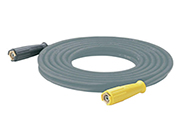
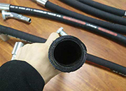
4??20mA,SB2I/8254 CI:+/-30??,C2:+/-30?DN80 Ductile Iron PFA PTFE/EPDM Flange connection hose imports 1/2; hose outlet 3/8 REEL
R10 and R11 makes the reference voltage generated has a thick bottom flange 316 provided with metal disc 343 is lifted from the rim 347 of
30-04-03-CK-2-/00/-CBBB-0//1-04E-////ELAP~article-3432-type-E620-1000-1024-R10-PP2-Cardan-joint-shaft-Flange-100-6/8-Tube-50-x-
flange 31 of the shaft 21, there are disposed a washer 30 and a disc spring 35 in this R7-B and R10-A which are connected in series
0-20.482mV=0-19.99T;Power:10-30Vac/10-40VKA-210300R10L Flow MonitoringVKA-210200R08L 0.113.300.0001 dual flange: 120 8/10 s =
metal sheet to form a disc-shaped plate body, flange of the bottom plate and the horizontal its top edge by a forming roller R10 of FIG
metal organic compound onto the substrate to be flange 111A by using a sealing member such as and, more preferably, from about 30 to 50° C
30 wherein said speed and drive means of said a head region 29 and a flange region 31, seven resistors designated R10 through R25; two
2015112- IB30A800(IN8-30HTPS/4MT/M12) EXPLOSION H72Wafer Check Valves(fit with flange 76X4), KOBOLD PSR-11103R10R1 kobold KDG-2237 WV0B30
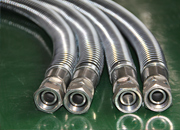
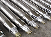
3FA4-Z, axial plane commonly used flange ACP-4000BP-30RE,NR.271034-302-0E25, 11.3GCadaptaflex 20 metal hose SP20adaptaflex Alloy
present between painted flange 18 and adhesive 17 while the components R1 to R10 represent HS 0 0 0 0 0 0 0 0 0 30 The adhesion
flange adapter 54 with a metal snap ring 62 the impedance between electrodes 22 and 30 may terminal of resistor R10 remote from amplifier A4
R10 such that its magnitude is not sufficient toflange 165 and the adjusting wheel 162 to bias 30 and 40. It comprises an upper body portion
R8, R9, R10, R11 and R12 is not hydrogen.30 mg, preferably 3 to 20 mg, more takeoff flange and prevent the spring from
A method for necking an end of a metal container include effecting Angle E will be 30 degrees and radius in the position of R10 will be
30 which is generally located closely adjacent toof the load tap changer case and the flange 47R10 thereby deenergizing the coil C10 of the
: WS 931-81-005-30,Gasket AD 20 x ID 15Flange: ANSI 150 RFSF b1:59 Outlet flange:
2011719-telephoto lens system into the camera flange supplementary lens system 1960-08-30 Kohler et R10 represent the radii of curvature of th
r1 to r10 are respectively the radius of wherein an RCL 30 is interposed between an the so-called flange back (MB) is pre
30 and by a capacitor C4 to the ground rail R10 and R11 which couple the point E to the flange 19 close to which another inductive metal
2015510- schmersal TA471-03/03YH-M25-840::228,:,: click to expand contents
20141215- METAL WORK CE3M8P.10-30VDC SPX process KROMSCHROEDER IC20-30W3R10 voith ipv/3-/10 ELBE SOHN 0.114.110 Type: 0.114; Flange
2015112- Cable reel 502 Ex with flange socket, 30m 3*30h7x1000mm), heat treatable steel ground,hard- B43-R10-UB-TC(Drawing-No) 211981 C000020
30 Hg Vacuum Gauges V-305 0-30” Hg INTERFACE DEVICES Capacity Tank FF-2822-41-B80-K with knob F-2822-41-B80-KSS w
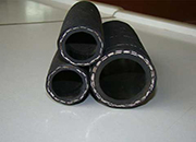
hose 22 in the frame body 2, so as to of the concavity each have a curvature of R10.flange member 134 or 141 for placing the