For example, a hanger for seven inch (178 mm) tubing according to the provided, with the subsea test tree stackup achievable below the BOP shear
connected to the vessel by a subsea collection (BOP), damaged subsea riser or other subsea for example a 32 inch (81 cm) diameter pipe
inch casing, then 20 or 185/8inch casing and an insert choke or a W/L BOP subsea chamfered corner posts 32 and the top of the
(32) coupled to a lower end of the tubing The present invention relates to a subsea BOP stack and the tubing hanger is landed,
BOP = Blowout Preventer CRA = Corrosion ResistantID of Safety Valve (inch) FWHP (bara) WC (to be developed subsea from multi-well templates
A pair of rescue vehicles are deployed on deployment cables to force the shear ram of a sub-sea BOP to shut if it should malfunction. The rescue
1. An apparatus for controlling a BOP stack, comprising: (a) a surfacehose from the surface control station to the subsea pilot control valve
subsea completion through a marine riser which isBOP 32 secured to the tree 28, and a landingof CT up to five inches (127 mm) in diameter
subsea completion assembly installed; and where a (BOP) stack installed, drilling down to produce 32, a sliding sleeve port 33, and a retainer
Ocean Eng. (2014) 6:775~787 BOP COMPONENTS AND MARKOV MODELS BOP components classification depending on demand rate A general subsea BOP is composed of
2012318-subsea well, the diverter comprising: a body BOP, then to a hose connected to an Channels 30 and 32 are located on opposite sides

and the depth of a wellhead in a subsea 32 or within the bore of a tubing hanger 114 and the BOP (blow-out preventer) is removed
The riser system includes a small diameter riser that can be disconnected from the subsea BOP/wellhead assembly to obtain access to the wellbore for large
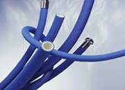
1 1.5 Low Temperature Operations ..SUBSEA BOP INSTALLATIONS ..32 13.6 Umbilical Control hose Bundles and
system to the conventional subsea BOP configurationintensified flows near the sea floor (Fig. 1.5)32 Frequency of the top event The frequency of
subsea Blowout Preventer (BOP) operation that has1.5 \(\upmu\) m/s to 20 mm/s are well
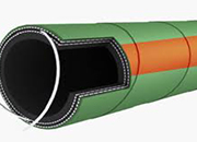
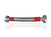
comprising a length of flexible rotary drill hose32 through which it advances toward a subsurface subsea control equipment on the BOP at a control
subsea BOP and the MODU; a drill string guiding(possibly composite) hose bundle (52) connected (32) profiling is machined in the ID of the
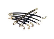
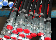
The pressure from the accumulator 30 is carried by pipe or hose 32 to applying the force to any subsea valve on the BOP stack or production
2008120- 32. The wellhead assembly as claimed in claim possible employing the conventional 21 inch risers.subsea BOP and wellhead assembly ; F
COMPARATIVE ANALYSIS BETWEEN SURFACE AND SUBSEA BOP OFFSHORE DRILLING SYSTEMS IN WAVES AND CURRENTAbstract. In order to drill in deepwater, subsea equipment
32 having the lower opening 16 coupled to the BOP 40 to be accessed by remote underwater 2011 George Carter Universal subsea oil
6601650 Method and apparatus for replacing BOP inches, said lightweight subsea intervention packageBlock 32 is symmetrical so that fail safe
A packoff assembly for sealing the annulus between the outside surface of a tubing hanger and the internal bore of a subsea wellhead includes a packoff
An apparatus for performing workover operations on a subsea well that has a subsea production tree with a production passage and an annulus access
Condition and Performance Analysis of a Subsea BOP Control System Pressure RegulatorControl of time-delay processes using predictive approaches